THERMAL STRAPS
THERMALLY CONDUCTIVE VIBRATION ISOLATION
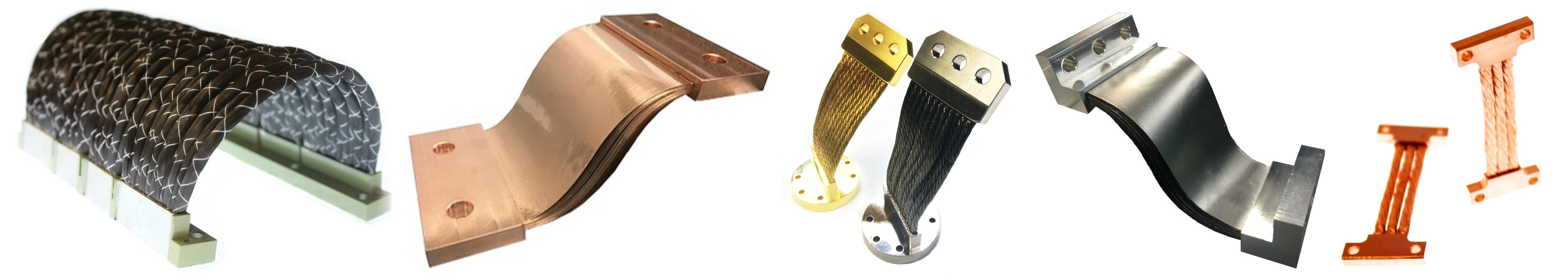
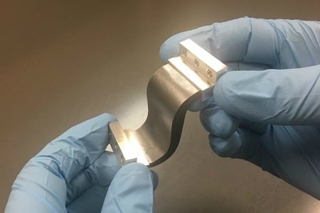
 Thermal Straps, sometimes referred to as "Flexible Thermal Links," "Thermal Braids," or "Heat Straps," are passive heat transfer devices consisting of two or more end fittings ("terminals" or "lugs"), and a flexible conductive material connecting them. They transfer heat between two or more locations (a heat source and sink), while mechanically decoupling rigid structures or instruments that require vibration isolation. The most commonly used conductive materials are copper cable or foil, aluminum foil, and graphite or graphene sheets or fiber bundles.
Thermal straps are unlike all other passive heat transfer devices (heat fins or bus bars, for example) or active devices (such as heat pipes or thermal switches). Because of their flexible nature, inherent vibration isolation, and lack of fluids or electronics, thermal straps are unique thermal control devices that offer an optimal balance between performance and flexibility, without the risks (or high prices) associated with rigid solutions or active cooling systems. As a result, they are a favorite for waste heat removal and vibration isolation for equipment such as cryocoolers, star trackers, photonics systems, and cryostats when movements from shock, vibration, mechanical function, and thermal expansion or contraction occur.
 Additionally, thermal straps can be paired with other vibration isolation systems or heat transfer devices, such as heat pipes, to provide additional attenuation and heat transfer, and in some cases, can be directly integrated with these products. To learn more about the differences between straps and heat pipes (and their advantages & disadvantages), read our blog: Thermal Straps vs Heat Pipes and Vapor Chambers.
Thermal links/straps existed in many forms for decades, ranging from crude linkages or shunts made from welded, crimped, or soldered copper braid or sheets (often used in automotive, LED, or electronics applications), to the highly efficient and precision manufactured straps available today for spacecraft, defense, and cryogenic engineering applications. Which strap type and level of quality you choose will ultimately come down to the operating environment, performance requirements, tolerances, and your end product's price point.
WHICH THERMAL STRAP IS BEST FOR YOUR APPLICATION?
TAI offers multiple thermal strap products because no single strap material or design is ideal for all applications. Each option offers a unique combination of thermal performance, flexibility, durability, vibration attenuation/damping, and mass, which customers must consider (and different applications are better suited to different materials).
The table below outlines some of the most common applications, their operating temperatures, and the commonly used strap types:
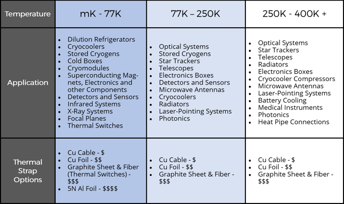
Though the application and operating temperature are important, there are several additional factors to consider when identifying the ideal strap material and configuration. Your program will also need to identify and weigh the following when determining the optimal strap solution:
| •MASS LIMITATIONS | •VIBRATION TRANSMISSION |
| •VOLUME RESTRICTIONS | •OPERATIONAL ENVIRONMENT |
| •THERMAL CONDUCTANCE | •FINANCIAL COSTS/BUDGET |
| •CTE/MATERIAL MISMATCH | •STIFFNESS REQUIREMENTS |
| •RANGE OF MOTION | •SPACEFLIGHT HERITAGE |
| •MECHANICAL FLEXIBILITY | •CLEANLINESS REQUIREMENTS |
| •LOAD BEARING REQUIREMENTS | •LIFE CYCLE BENDING / FLEXING |
To learn more about our product offerings, download our catalogs today, and download and complete our Thermal Strap Questionnaire to get your inquiry started. Remember: all front end (pre-purchase order) design work is always free of charge, and our engineers and strap experts are here to assist you at every step along the way!
|
|
|
|
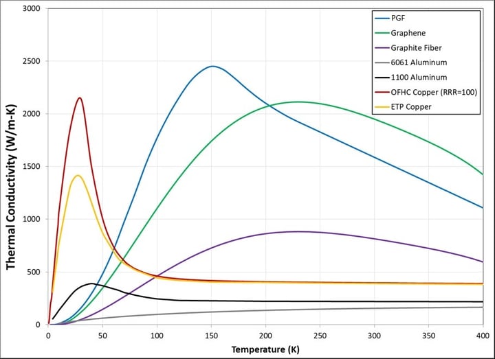
MATERIAL CONDUCTIVITY COMPARISON
STRAP TYPES - BENEFITS AND LIMITATIONS
METALLIC FOIL AND BRAIDED STRAPS
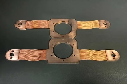
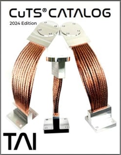
Copper Cabled Thermal Straps (CuTS®)
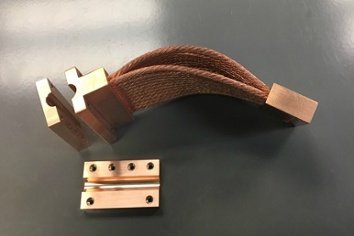 Copper braid or cabling straps are often soldered, brazed, or welded. However, these assembly processes are not ideal for most aerospace, semiconductor, or cryogenic engineering customers. This is because they result in exponentially higher thermal resistance losses, and significantly increased stiffness (as the heat from these processes wick up the cables). Increased stiffness can transfer vibrations and damage equipment. To avoid these negative drawbacks, TAI manufactures our straps via a swage ("cold press") process. This is because a cold press, heat-free assembly method offers unmatched efficiency and preserves the flexibility of the conductive materials used in a thermal strap.
When considering flexibility, durability, and performance, a copper cabled strap is the preferred, and most frequently used, in all industries and applications. Further, TAI's exclusive OFHC UltraFlex™ I and II cabling (used on all standard and custom CuTS®), offers customers the optimal combination of flexibility and thermal performance. CuTS® offer flexibility on all axes, and can handle exponentially greater loads and life cycle flexing than any other strap or material type.
-
Mass: Copper has a higher density than other conductive strap materials, and in extremely mass-sensitive applications, a graphite strap may be your best option. However, TAI can substitute AL 6061 for the end fittings in any CuTS assembly, thereby reducing the total mass of a strap by 40-60% on average). It is important to note that while aluminum is less dense than copper, aluminum foil straps are not always an ideal alternative (when mass is a concern). Aluminum offers a fraction of the conductivity of copper, and stacked aluminum and copper foil straps must be designed into longer C and U-shaped installation configurations (with at least a 180 degree curve), in order to provide any flexibility on all 3 axes, and in full S-shapes to achieve a wide range of motion (i.e. typically greater than 1mm), on the lateral/transverse axis. As a result of this longer length, they must be made with more sheets to match the thermal performance of a copper cabled strap, thereby increasing the mass.
-
Copper rope straps—even those made by TAI—can be stiff if multiple rows are incorporated into the design AND the cable length is less than 1.0 inch (25.4mm). At these shorter lengths, cables continue to offer superior flexibility over stacked metallic foils, but the increased stiffness of the assembly is noticeable.
-
Cross-sectional area: a cable (or braid), by its very nature, is not as densely-packaged as a stack of metallic sheets. As a result, cabled straps may not meet your thermal conductance requirement in certain volume-restricted applications.
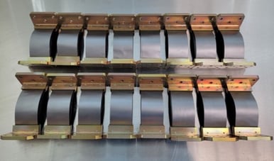
Copper & Aluminum Foil Thermal Straps (CuFS®, AlTS)
 Volume-restricted applications (requiring high thermal performance), may benefit from a stacked metallic foil configuration. However, there are a number of trade offs to consider:
Limitations:
-
Stiffness: all metallic foil straps are stiffer (and on each axis), than equivalent copper cabled configurations. As a result, foil straps are designed in "S" and "U" shapes, in order to provide flexibility on the compression and lateral axes. However, this increases the length of the strap, which negates the benefits of using foils to begin with. In fact, most engineers are able to substitute a much shorter copper rope or graphite fiber or sheet strap when considering a foil configuration. This results in reduced or equivalent mass, while offering equivalent—or improved—performance. Additionally, replacing a foil strap with a copper cabled configuration significantly reduces the price.
-
Many conventional assembly methods (brazing/soldering/welding), dramatically increase stiffness.
-
Foil straps typically cost 2-5x more than copper cabled straps. Not only are the materials more expensive, but the assembly process is more complex and involves additional steps (thus, the higher price).
In many cases, foil straps are not the ideal solution. However, there are specific applications and environments in which they may offer benefits over a graphite or copper rope strap.
GRAPHITE & GRAPHENE STRAPS
There are multiple carbon-based thermal strap solutions to consider in the industry. Initially, flexible graphite thermal links were initially used only for spaceflight applications operating between 230 - 400K However, high conductivity graphite materials (like pyrolytic graphite film, graphene layered foils, and graphite fiber), also offer a unique set of benefits over a wide range of operational and environmental conditions. As a result, they are now being incorporated into terrestrial and spaceflight cryogenic applications. Each carbon-based thermal strap product offers a combination of mechanical, thermal performance, and financial costs to consider. It is important to note that graphite fiber and sheet should not to be confused with rigid Annealed Pyrolytic Graphite (APG), which is not flexible enough to be used as a true thermal strap, or graphene layered foils, which fracture with movement.
One of the most significant differences between graphite and metallic-based thermal straps is how heat is transferred through the materials, and what can be considered the "bottleneck." In graphite straps, the heat transfers in-plane with the graphite sheets or fiber bundles. As graphite offers exponentially greater conductivity than copper or aluminum, the fitting size or "footprint" is largely irrelevant (plays little part in the overall performance). Instead, the primary purpose of the fitting is simply to act as a bracket that contains the graphite and attaches it to the interfaces. As a result, the total length of the graphite material will significantly impact the thermal conductance of the assembly.
This differs from copper and aluminum thermal straps, in which larger fittings can increase the conductance of the strap, and the "bottleneck" is the length of the flexible rope/braid/sheet material (given it's cross section compared to solid fittings). Because of this, assuming the mass requirement is not exceeded, metallic straps can be made with longer fittings and a shorter flexible portion length (rope length). In some cases, using this approach, a copper thermal strap can meet or exceed the thermal performance of a graphite strap.
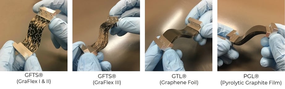
Graphite Fiber Thermal Straps (GFTS®)
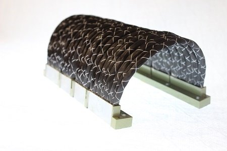 Graphite Fiber Straps are made with GraFlex™, a bundled "toe" or rope of fibers with a material thermal conductivity of 810 W/(m-K). Fiber-based straps are more durable and lighter than carbon film/foil straps, and they offer lateral flexibility and deflection without needing to be installed in S or C/U-shaped configurations with a 180+ degree arc. The most notable attributes of graphite fiber straps is their high conductance to low mass ratio, and their unparalleled ability to attenuate and absorb vibration. The average GFTS® assembly is lighter than an equivalent carbon sheet strap, and just 1/5 - 1/10 the mass of a comparable copper rope strap.
Limitations:
-
GFTS® products—while more robust than graphite and graphene sheet/foil straps—are delicate, and more fragile than metallic straps.
-
Fiber-based strap assemblies provide a fraction of the performance of their foil/film-based counterparts.
-
GFTS® assemblies, like metallic foil straps, need to be designed and assembled into their installed configuration/shape, and do not offer an extensive range of motion on all axes (like a copper cabled strap).
-
While they offer 3 axes of flexibility/deflection, GFTS® assemblies are best-suited to applications requiring less than 25mm of deflection on each axis, and are stiffer on the vertical and compression axes than a PGF-based strap.
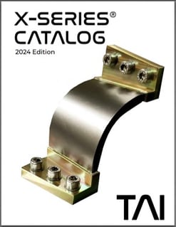
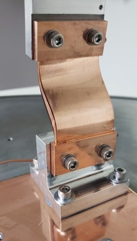
PGS & Graphene Thermal Straps (PyroFlex™ & GTL™)
 Pyrolytic Graphite Sheet / Film (PGS / PGF) and Graphene Layered Foil/Sheet Flexible Thermal Links offer the highest thermal performance of any of the strap products (above ~80K), ranging from 1,400 W/(m-K) - 1,840 W/(m-K) at a 300K operating temperature. Their compact profiles also make them ideal for volume-restricted applications. Though there are tradeoffs to weigh when considering a PGF or graphene strap, they offer a unique combination of flexibility, low mass, and thermal performance.
TAI's PyroFlex™ Graphite Film Straps offer the highest thermal performance of any carbon-based strap at cryogenic operating temperatures (with performance peaking at 150K). They are an effective replacement for aluminum foil straps down to operating temperatures as low as 65K (and provide equivalent performance—at a lower mass—to OFHC copper thermal straps between 70 and 80K).
Limitations:
-
All stacked pyrolytic graphite and graphene foils/sheets/films are fragile. These can be damaged if flexed on the lateral axis (when not designed for this type of deflection), or if improperly handled or used. Carbon-based sheet thermal straps must be installed in S-shapes, or curved 180° (or near 180°) arcs (C or U-shapes), in order to provide lateral deflection / coplanar to the sheet material (though a 90° bend / "L-shaped" graphite sheet strap can usually achieve a 1mm lateral deflection).
-
Carbon-based straps are not ideal at operating temperatures below ~60K, unless the goal is to use them as a flexible thermal switch. Graphite thermal links can be used in addition to copper thermal straps, to reduce cool-down times of cryocoolers and cryostats, and then effectively cease heat transmission between 10-40K, depending on the material.
-
Graphite/Graphene Sheet/Foil straps are expensive. Graphite Fiber Strap products now sell for the same price as competing metallic foil straps. Graphite sheet-based products have somewhat higher material and assembly costs.
THERMAL STRAP FAQ
MEASURING THERMAL CONDUCTIVITY
Beyond heritage and qualification history, a critical factor when selecting a thermal strap supplier and product is understanding how the thermal conductivity of a strap is measured, and if the manufacturing process results in consistent quality and performance. TAI has been at the forefront of thermal strap qualification and thermal conductivity testing for nearly 30 years, and our conductance test and projection processes are highly-accurate. The following excerpt is from our standard work instruction procedures, and provides valuable insight into the test and calculation processes.
Measurement Basic Practices and Definitions
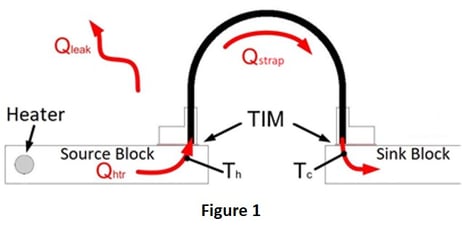
The basic premise of measuring the thermal conductance of straps is to apply a measurable amount of heater power (Qhtr) to one end of the strap while securing the other end to a heat sink. The temperatures of the heat source and sink blocks are then measured just under the interfaces of the strap’s end fittings.
Given that external heat leak paths to and from the strap under test are minimized and predictable, the thermal conductance of the strap can be calculated as:
Cstrap = Qstrap/ΔTstrap
TAI uses a thermal interface material (TIM) (HITHERM™ HT-1205) in order to minimize the thermal resistance at the interface between the strap’s end fittings and the source and sink blocks. This is done because we cannot always control or replicate the exact attachment method and interface used in the specific application and because we are mainly interested in the thermal conductance of the strap itself.
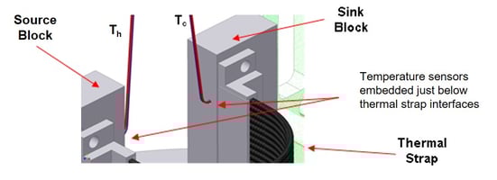 As shown in Figure 1 (top right), and Figure 2 (left), the temperature sensors are embedded in the heat source and heat sink blocks. This puts the temperature measurements directly within the heat flow path. The effects of the blocks, temperature sensor locations, and the bolted interfaces can be determined and removed from the reported strap thermal conductance once the data is reduced.
This measurement technique is important because temperature probes attached to the exterior of the end fittings do not result in accurate measurements. Externally mounted temperature sensors result in measurements that are outside of the heat flow path.
To minimize heat leak paths (Qleak) that can compromise test results, TAI uses these design and configuration practices:
- The thermal conductance test fixture is placed in a vacuum chamber which is evacuated to less than 10 mTorr in total pressure. A vacuum environment minimizes heat transfer due to convection and is accounted for in our thermal models.
- Source block supports are long, thin, and are made from low-conductivity materials (typical set-up uses thin PTFE cord to suspend source blocks).
- Heater and thermocouple (TC) leads are long and thin. TC leads are made from low-conductivity material and are accounted for in thermal models.
A radiation shield is not normally used in typical test configurations. Without a shield, the heat leak due to radiation is a straightforward calculation. With a shield, radiation would be reduced, but the heat transfer becomes more difficult to predict. TAI has experienced that test results with a radiation shield are highly variable and unpredictable. Therefore, we do not use a radiation shield in our thermal test configuration.
In our standard test configuration, we limit total heat leak to less than 3% of the total heater power for GFTS® and CuTS®. The total heat leak is calculated and taken into account when thermal conductance of the strap is reduced from the test data.
For the strap thermal conductance calculation, the heat leak (Qleak) through the various paths (wires, radiation, and source block support) is determined and subtracted from the measured heater power. The result is the heat flow through the thermal strap from source block to the sink block (Qstrap). The measured temperatures from the temperature sensors embedded in the heat source and sink blocks are used to calculate a raw thermal conductance (Craw). Craw is the value of the direct temperature measurements:
Craw = (Qhtr – Qleak) / ΔT = [(Ihtr)(Vhtr) – Qrad – Qhtr leads – QTC leads] / (Th – Tc)
The physical properties of the test blocks (material conductivity, heat flow area, depth of the temperature sensors) are used to calculate the thermal resistance due to the fact that the temperature sensors are not in direct contact with the thermal strap itself. Removing these effects gives the source-surface-to-sink-surface thermal conduction: Csc-sk, which includes the thermal resistance of the bolted interface, using the thermal interface material.
The thermal resistances across the bolted interfaces can be determined empirically using test data and the contact areas of the thermal strap. When the interface resistances are removed from Csc-sk, the resulting value (shown as CS) is the thermal conductance of the thermal strap alone. See Figure 3 for a detailed view of the thermal conductance values reported by TAI.
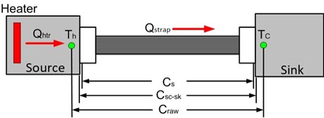
Pictured: Figure 3 - thermal strap conductance projection definitions.
Csc-sk is typically reported as it is directly related to the measurements obtained from the test configuration. Cs is also reported because it is the value of most interest to the end user.
To learn more about our standard thermal conductivity test procedures, contact TAI today. Our experts have standard work instruction packages for all of our strap qualification and processing procedures (stiffness, conductance, bagging & packing, etc.).
TAI's STRAP HERITAGE
 Our copper and graphite strap design, test, and manufacturing heritage spans three decades. It began with our own Scott Willen and Richard Jetley, who developed the first Graphite Fiber Straps (GFTS®), in SBIR Ph I and II contracts with the USAF in 1996 (this research was later published in Cryocoolers 11). GFTS® products gained popularity in 2011 - 2013, During this time, several dozen assemblies, designed and manufactured by TAI Quality Manager, Trevor Sperry, were used to cool the phased antenna arrays and data acquisition systems on the ORION spacecraft, and compressors on JAXA's Astro-H satellite. Since 2015, GFTS® have played vital roles in notable programs such as Boeing's CST-100 Starliner, NASA's IXPE and GRACE-FO satellites, ESA's Solar Orbiter, DLR’s EnMAP, and several other spaceflight missions (in addition to ground-based applications in the medical and cryogenic engineering industries).
Our Copper Cabled Strap (CuTS®) heritage began in 2004, with our first-generation solderless copper braided straps (offered until 2014). TAI was the first and only supplier to offer a fully customizable standard product line and catalogs, both created by our Director of Business Development, Tyler Link, in 2013. Two years later, TAI developed OFHC UltraFlex cabling, optimized end fitting design, and improved swage & final machining methods. In 2017, this new generation of straps was studied extensively by Fermi National Lab and other universities and laboratories (research was later published in volume 86 of the Journal Cryogenics, and co-authored by TAI's Tyler Link and Jamie Deal).
Work with Pyrolytic Graphite Film-based straps began in 2013, culminating in the X-Series® Strap; the world's first and only graphite and graphene sheet thermal strap standard product line. X-Series® PGF-based thermal links (PyroFlex™) were then space-qualified by NASA JPL in 2018. They advanced to TRL 8 with spaceflight qualification testing performed by Airbus and the DLR, on the Merlin program. PyroFlex™ straps now play vital roles in space flight programs for aerospace companies across the US, Europe, and Asia, and at NASA, JAXA, and ESA.